| 4CS fork kit installation instructions |
|
- Click on picture to enlarge.
|
|
We copied the rebuild instructions with mv cup here and created a new folder for all these images. Then we used find and replace so it draws these images from the 'images_4CS_kit_ install_mvcup' folder.
We don't use the mv cup anymore, but we will leave the install instructions up as we have 54 dyno and press tests using the kyb cup. We may want to refer back at some time. |
|
|
|
|
| |
|
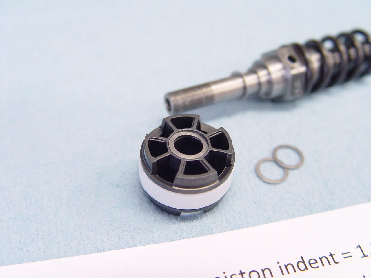
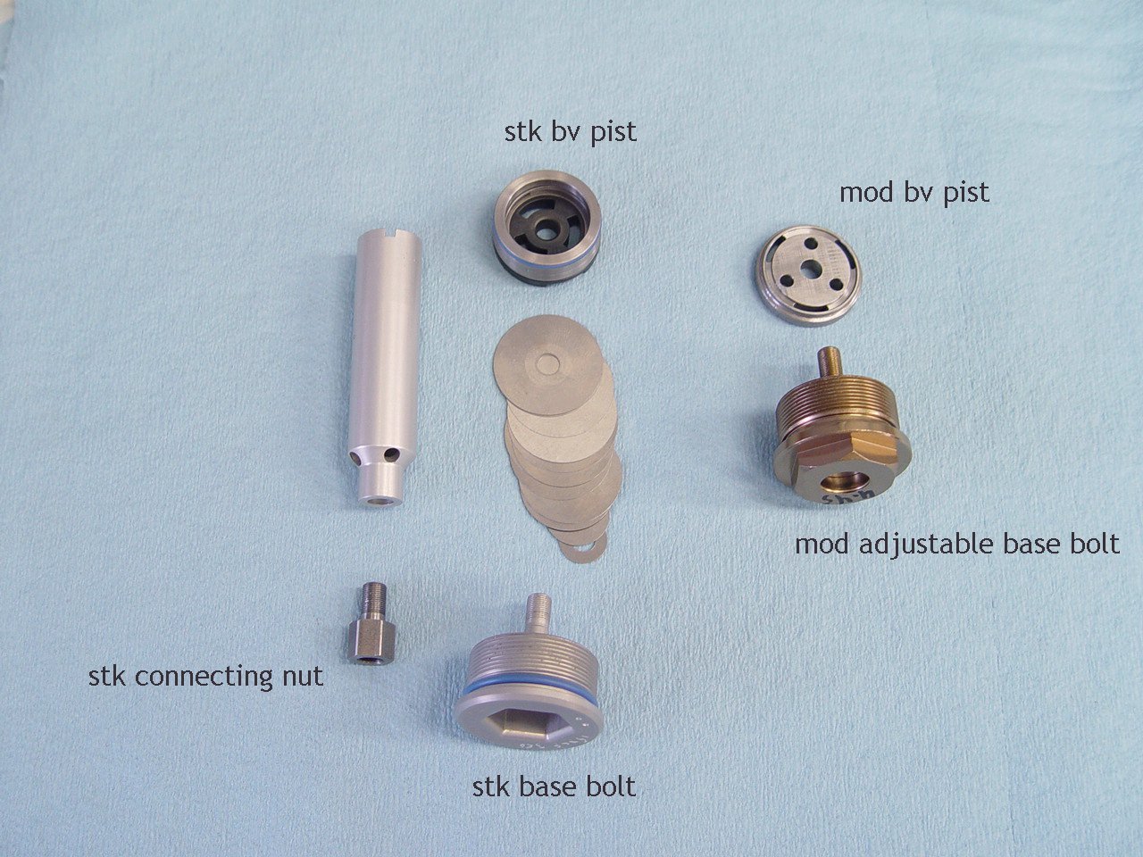
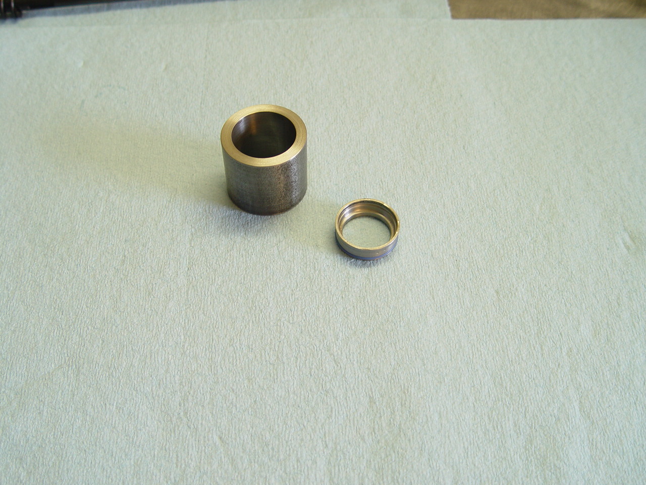
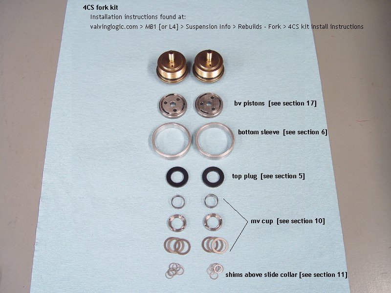
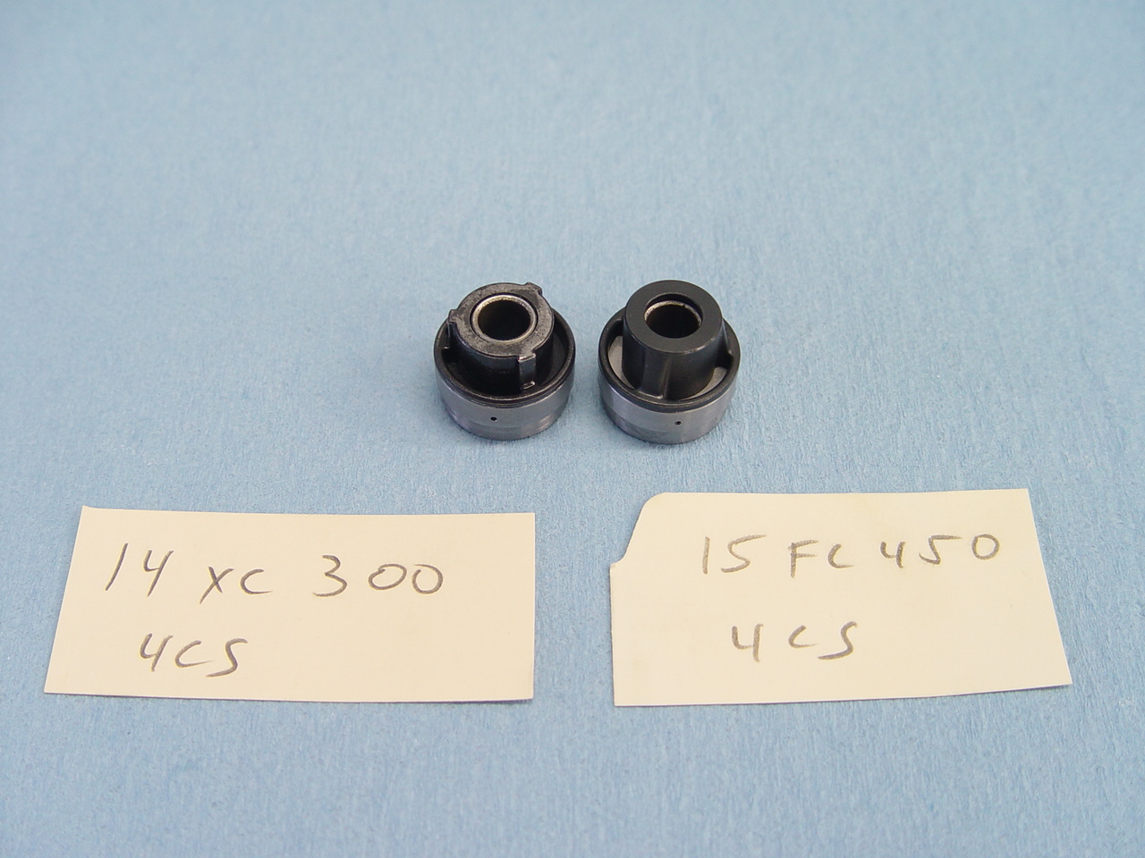
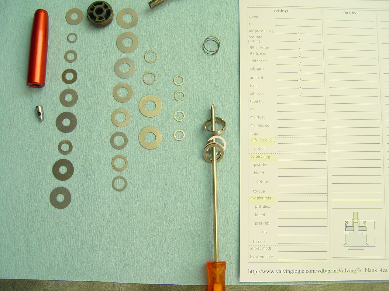
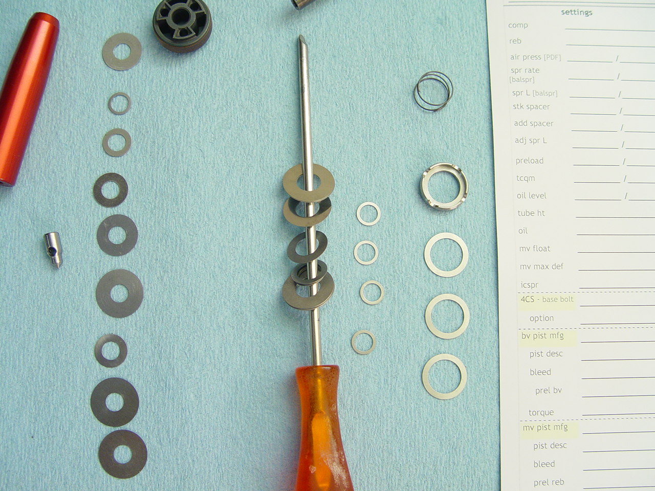
| 4CS kit pieces |
|
 |
Click on pictures to enlarge. |
|
|
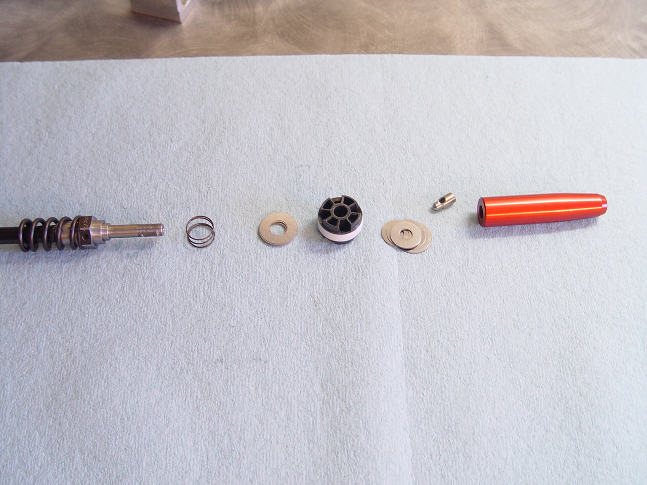
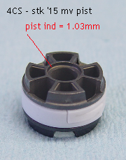
| 4CS kit - using stock mv piston |
|
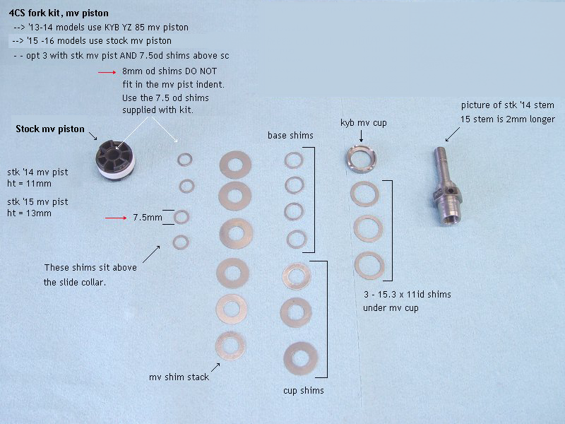 |
'15 and '16 models use the stock mv piston.
- stk '13-'14 mv pist ht = 11mm
- stk '15-'16 mv pist ht = 13mm
- [also see section 14] |
|
|
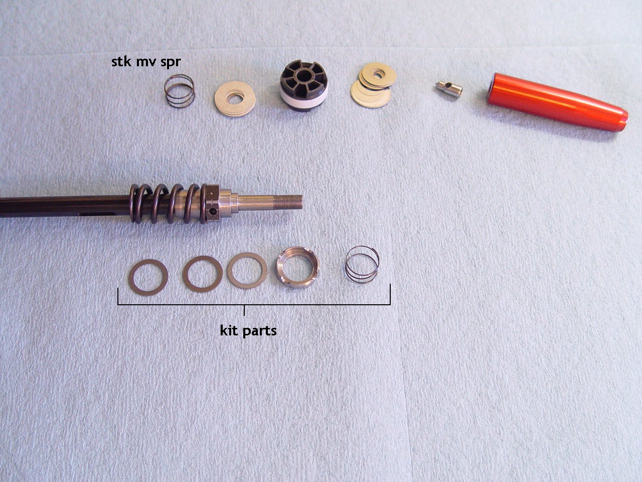
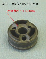
| 4CS kit - using KYB YZ 85 mv piston |
|
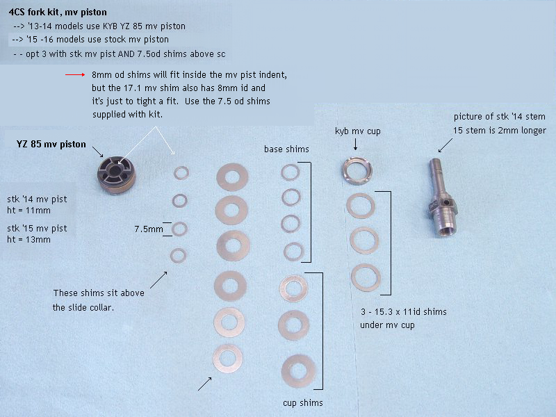 |
'13 and '14 models use the YZ 85 mv piston.
- stk '13-'14 mv pist ht = 11mm
- YZ 85 mv pist ht = 11mm
- [also see section 14] |
|
|
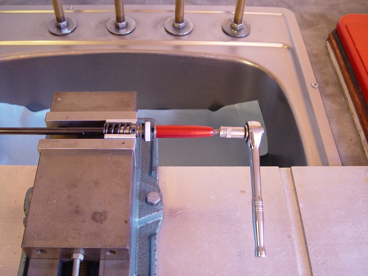
| 1) Lock 2 - 8 x .75 nuts together to loosen jamb nut. |
|
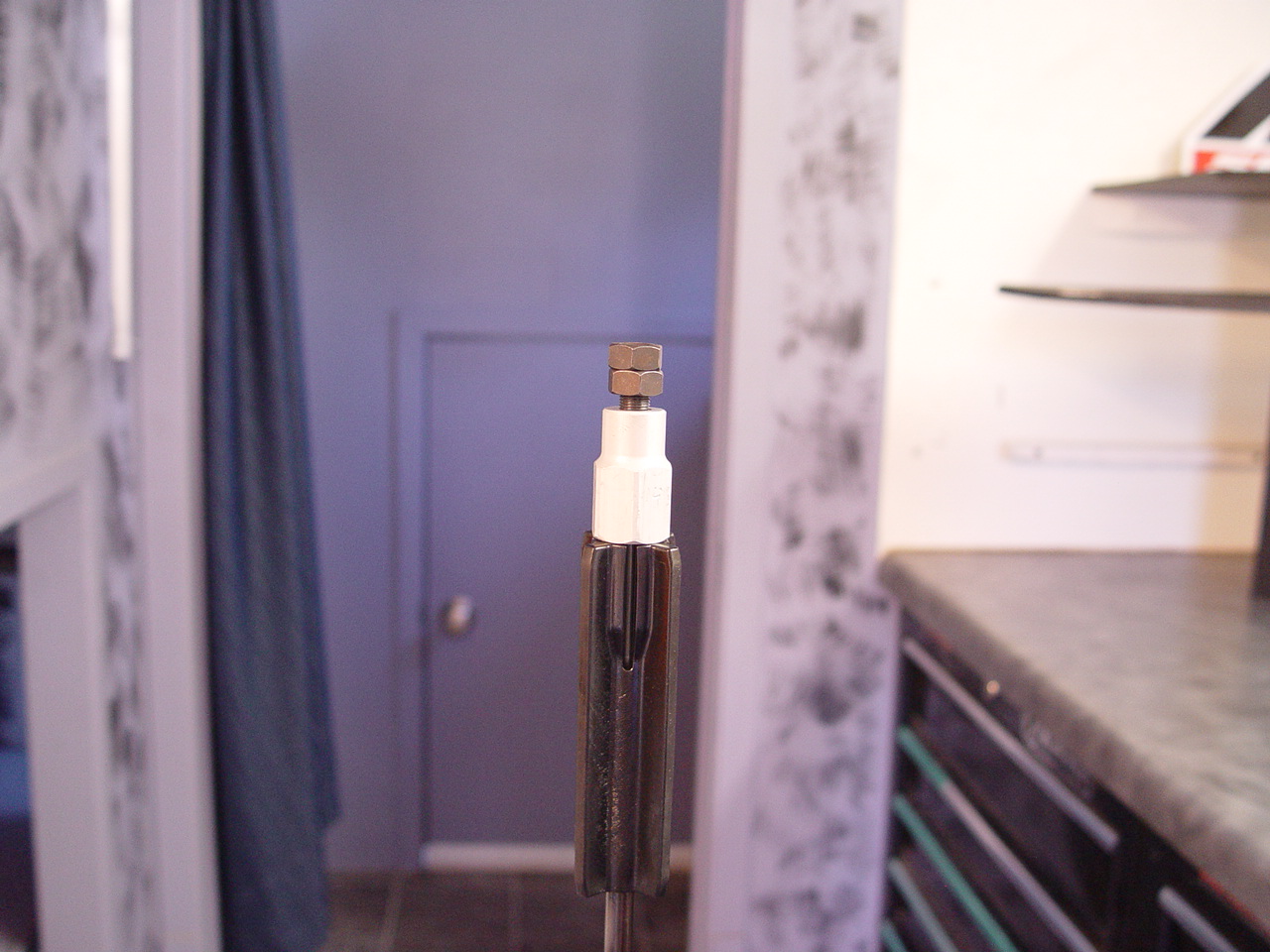 |
Click on pictures to enlarge. |
|
|
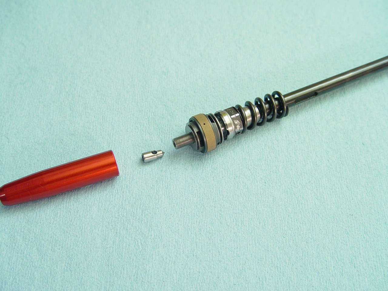
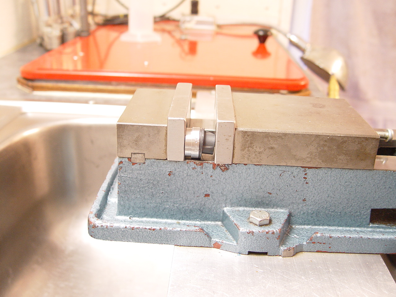
2) Remove base bolt. Pour out oil. Slide mv rod out the bottom.
|
|
| 3) Remove cartridge tube. |
[top] |
 |
Push ctg tube out from bottom. |
 |
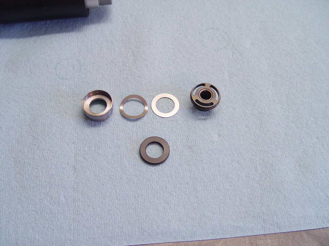
Remove plastic spring holder, metal washer and preload rings. |
|
|
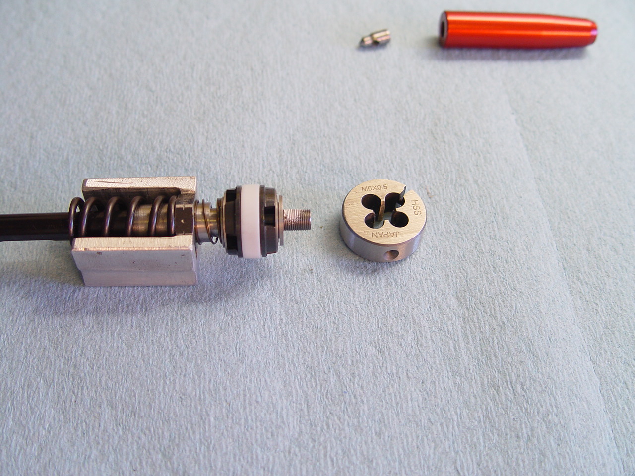
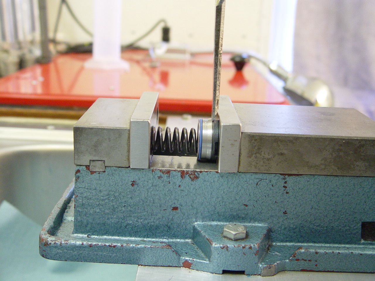
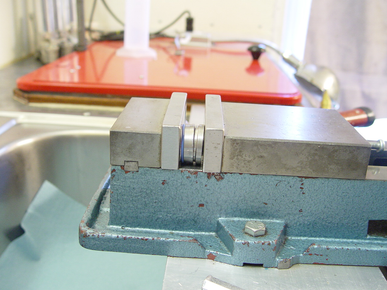
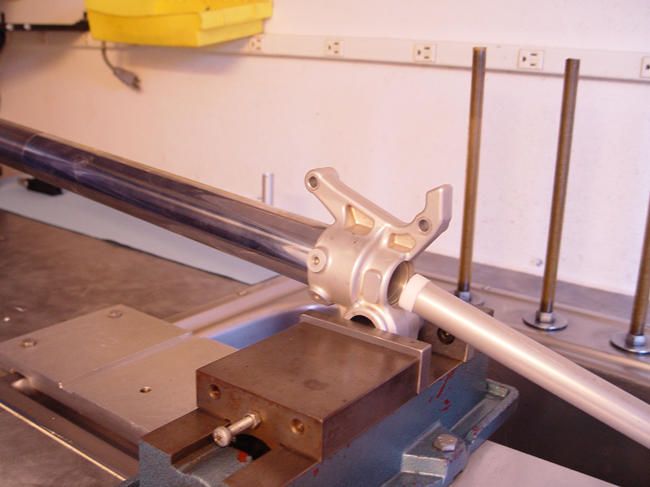
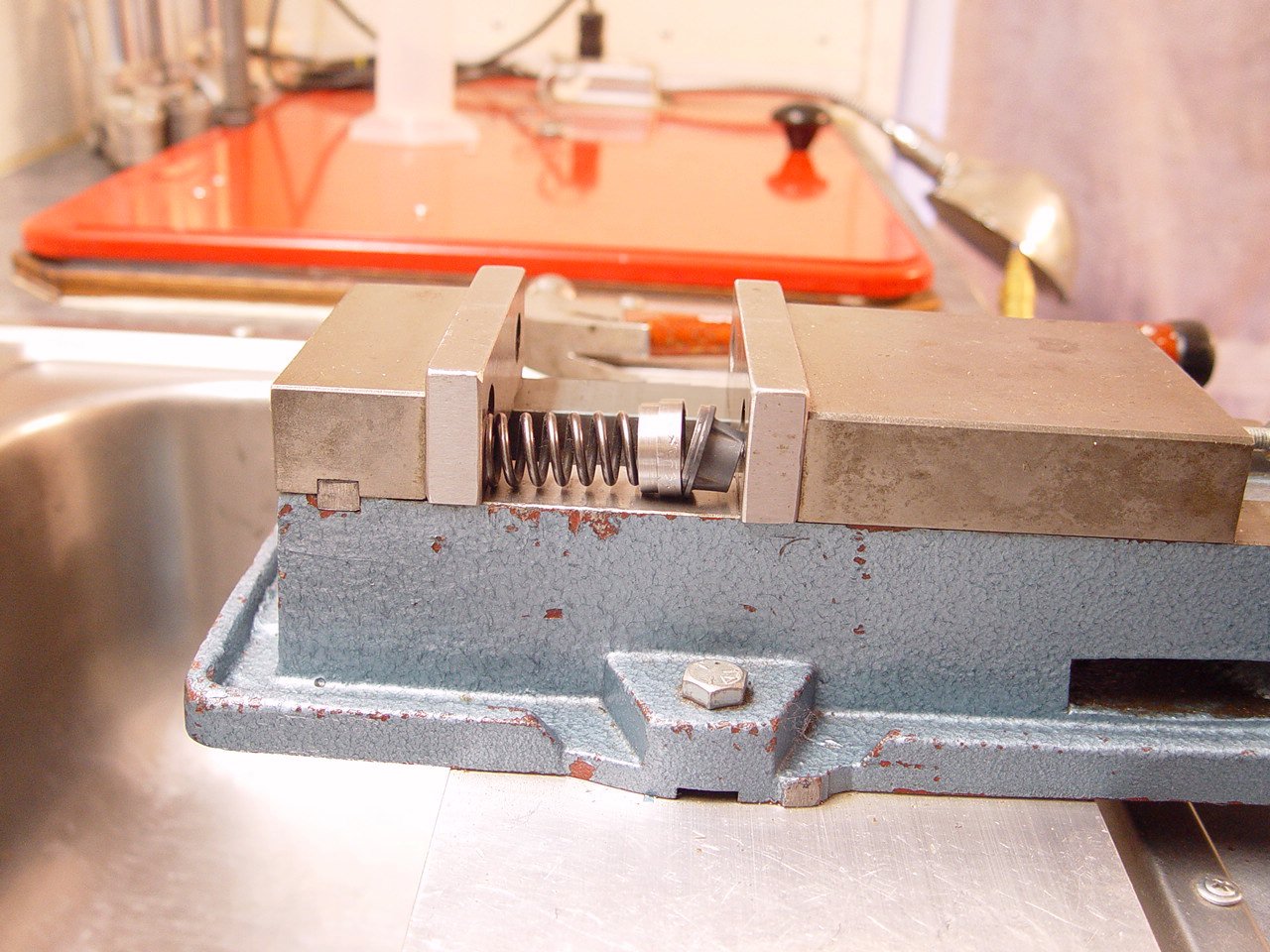
| 4) Clamp tube in vise with 24.6mm clamp block and disassemble. |
[top] |
 |
Remove the seal assembly. |
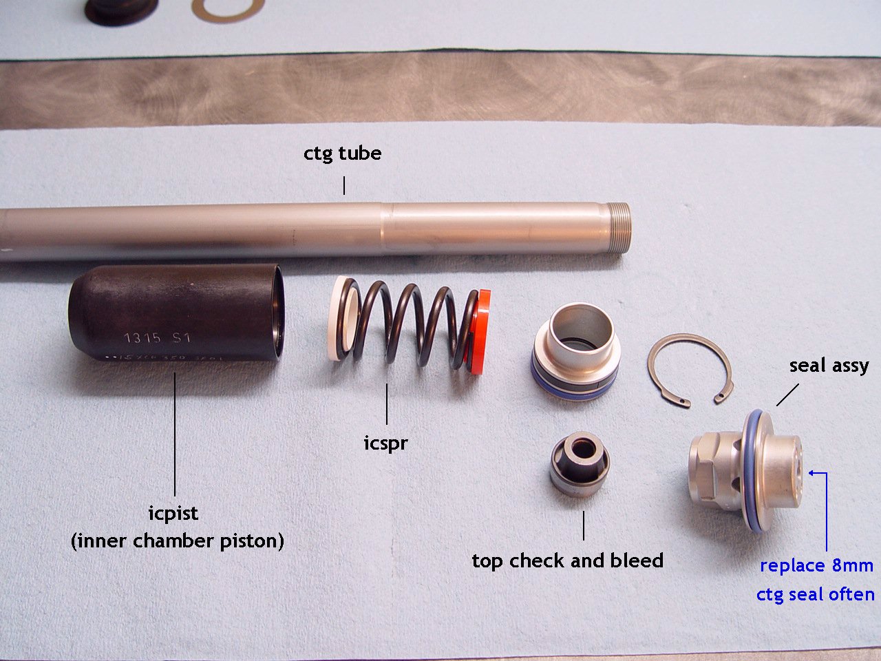 |
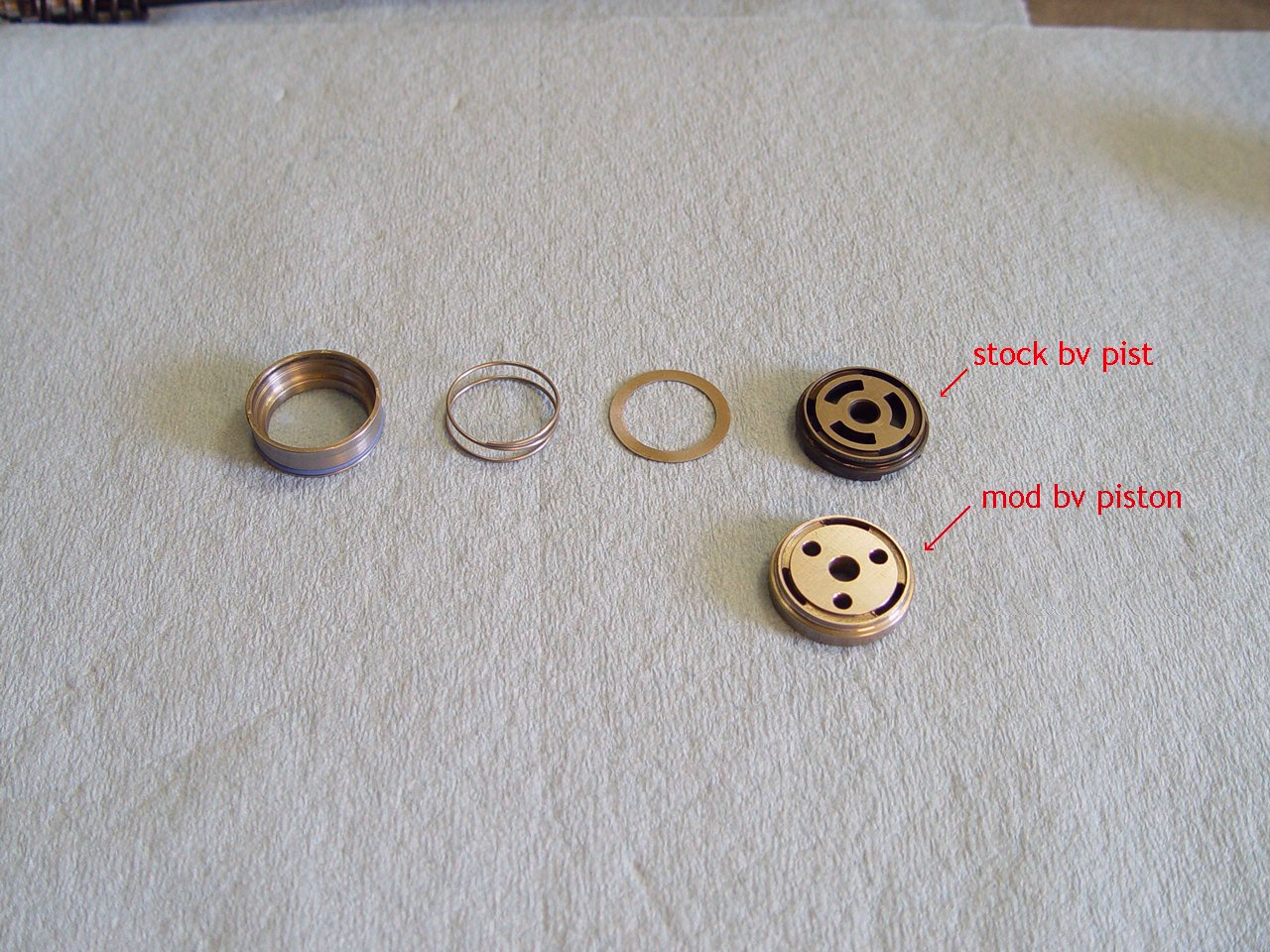
Remove seal assembly and slide off the icpiston (you do not have to disassemble the icpiston). Check for oil inside icpiston.
For some yet unknown reason, oil can accumulate in the icpiston. This fix is to simply clean the parts and reassemble. Not very scientific, but we haven't determined the cause.
We recommend replacing the 8mm ctg rod seal on a regular basis. No need if the forks are near new.
CAUTION!: Do not spray brake cleaners on the blue orings. It can remove the blue coatings on the oring surface. |
 |
Check subtank (left end with screw driver), some earlier units have been known to be loose. The subtank does not need to be removed for the kit installation.
If it's tight, it's on there with some good loctite. Don't worry about breaking it loose with this quick check.
If it's loctited and needs to be removed, heat should be applied. |
|
|
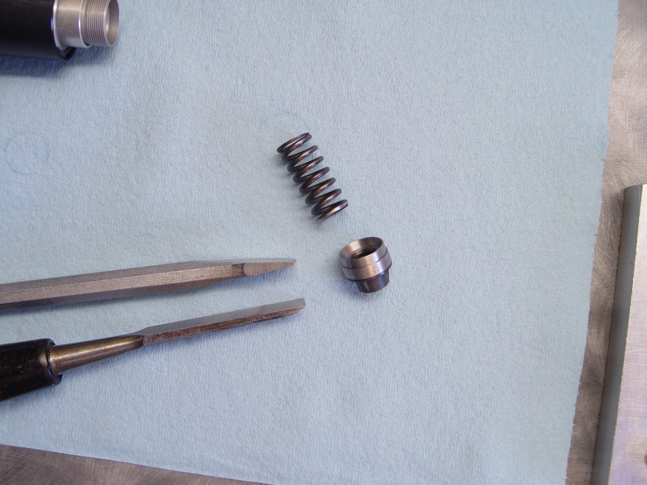
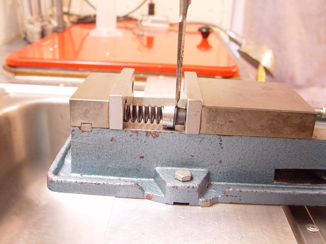
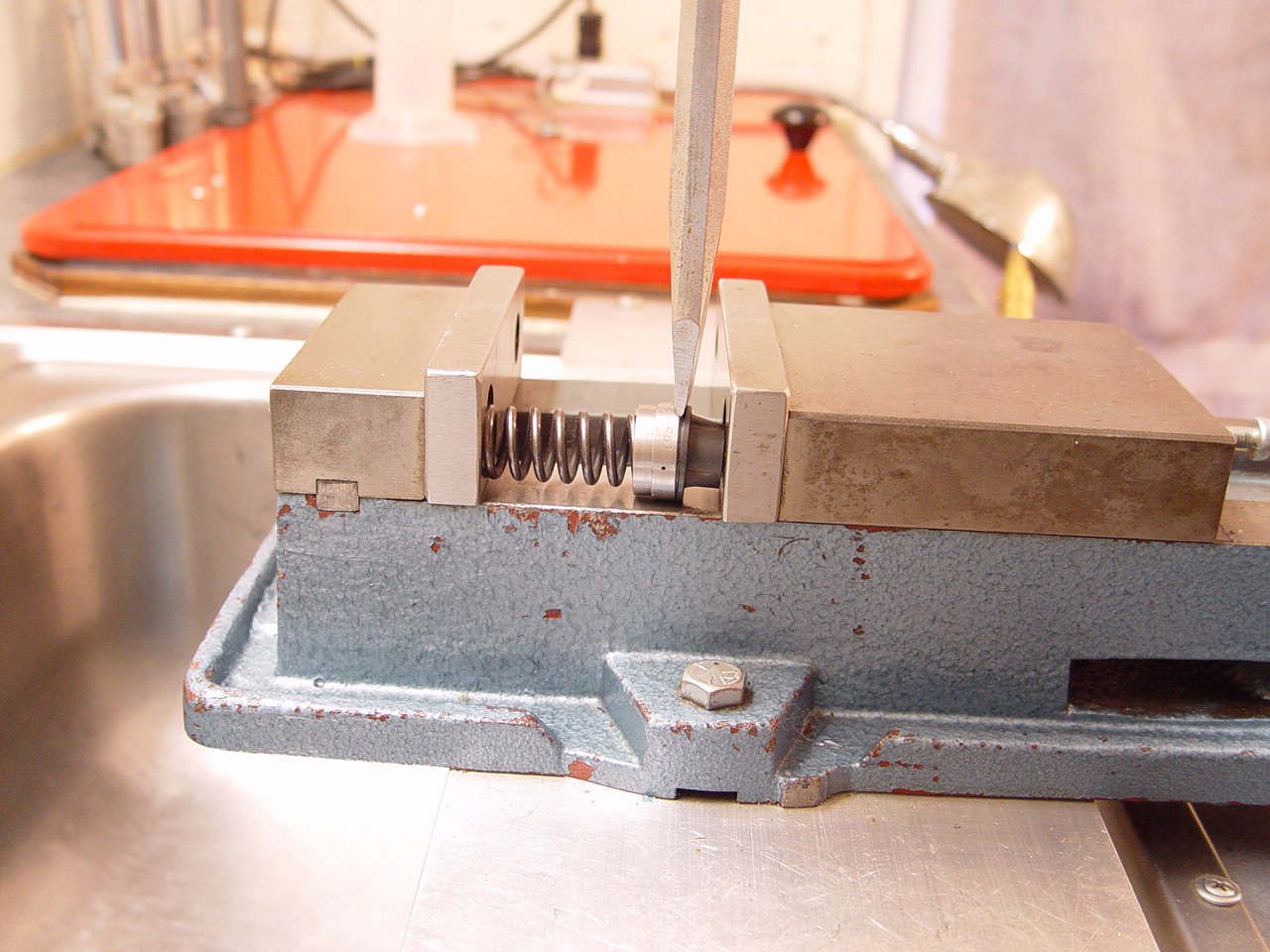
5) Split check assembly and install plastic plug.
---> The plastic plug closes the top check and bleed hole. |
[top] |
 |
Start with sharp wood chisel and progress to cold chisel. |
 |
Start with sharp wood chisel. |
 |
Finish with fatter cold chisel. |
 |
|
 |
The plastic plug replaces the metal check shims and wave washer. |
 |
Press in the plastic plug (do not use check shim and wave washer). |
 |
Press together the pieces. |
 |
NOTICE!: The 8mm bushing can pop out of the older style check assembles found in some '14's.
Our fix was to machine and press on a metal cap. We also tried loctiting the bushing in place, but are unsure how strong the loctite holds.
|
 |
The factory corrected this in '15. |
|
|
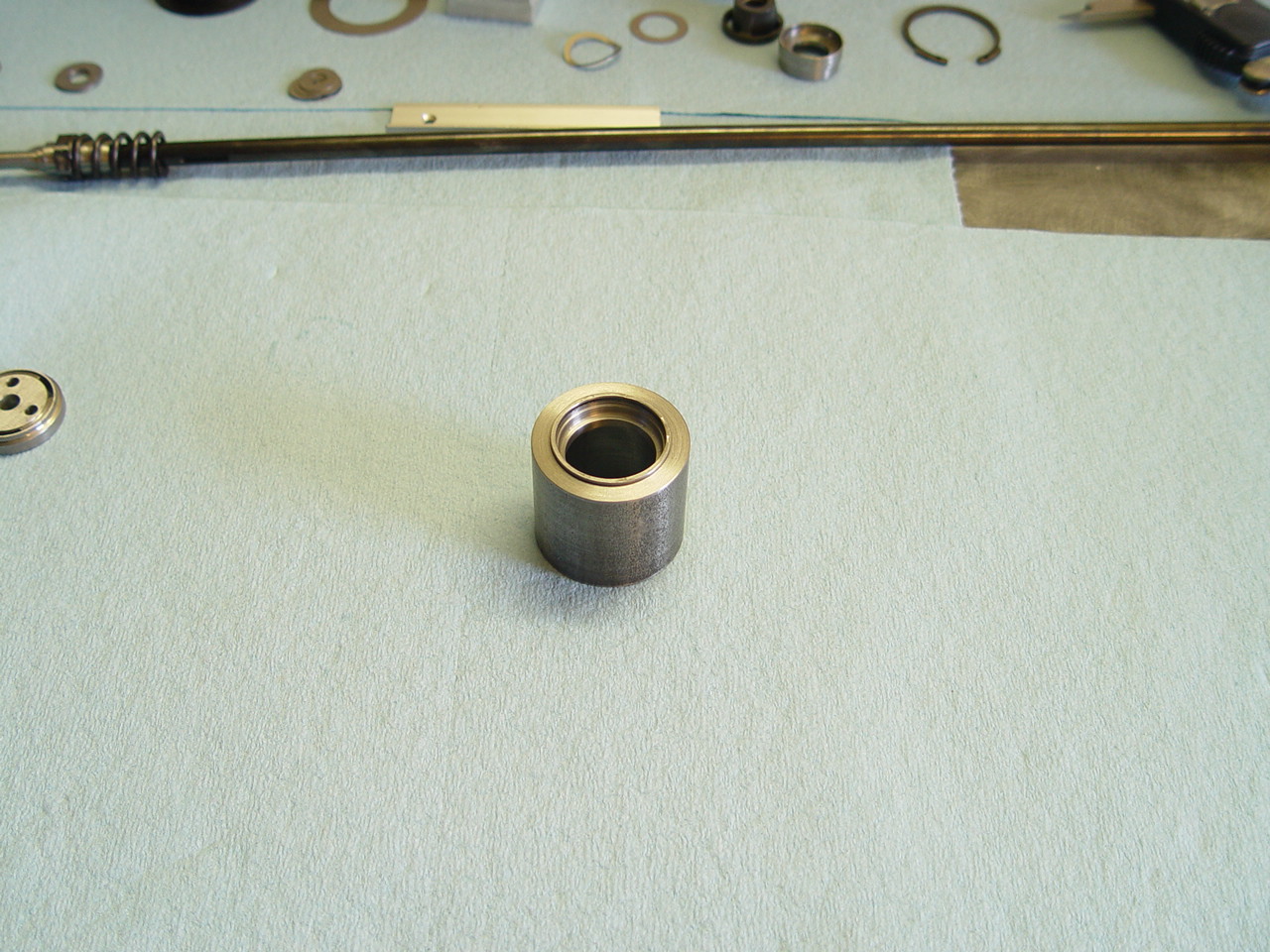
6) Install bottom sleeve with loctite.
---> This closes the bottom bleed hole. |
[top] |
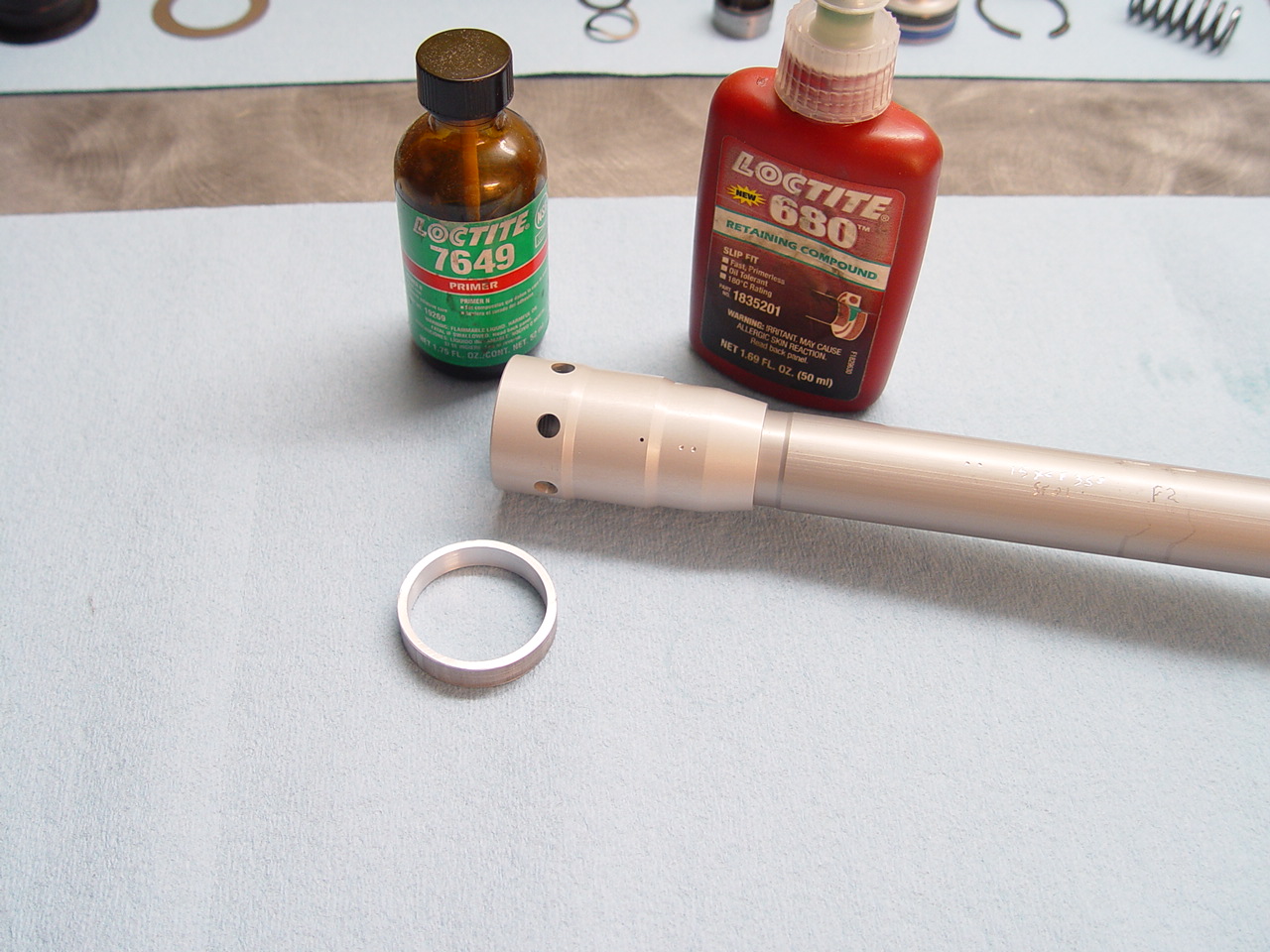 |
A primer should be used when dealing with "inactive" metals such as anodized aluminum. We recommend Loctite 7649 primer. For maximum hold, we also use Loctite 680 retaining compound. But 680 is considered permanent, is expensive and hard to find, so red will do.
NOTE! The primer is a necessity! Also note that the primer can greatly reduce working time to as little as 3-5 seconds.
[click for additional info on primer] |
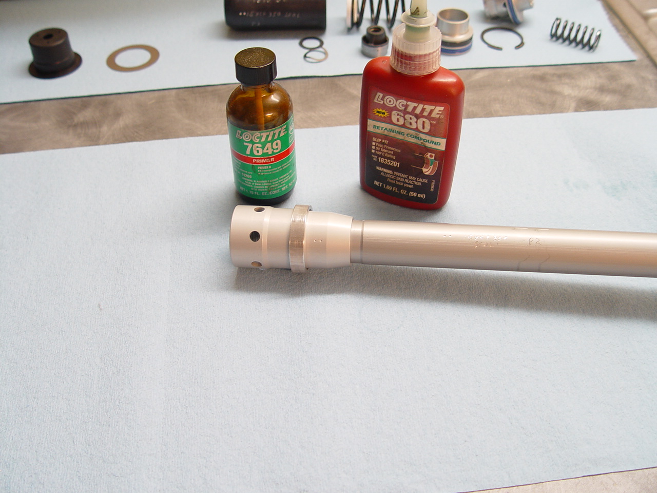 |
Apply loctite and position the aluminum sleeve over bleed hole.
The aluminum sleeve does not press fit, but is somewhat loose fitting. This makes for easier installation and gives a bit of space for the loctite. |
|
|
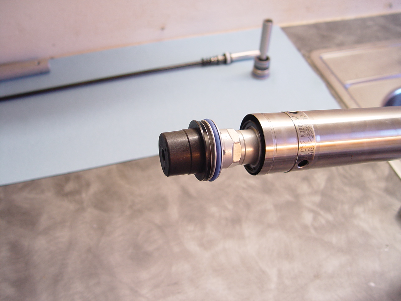
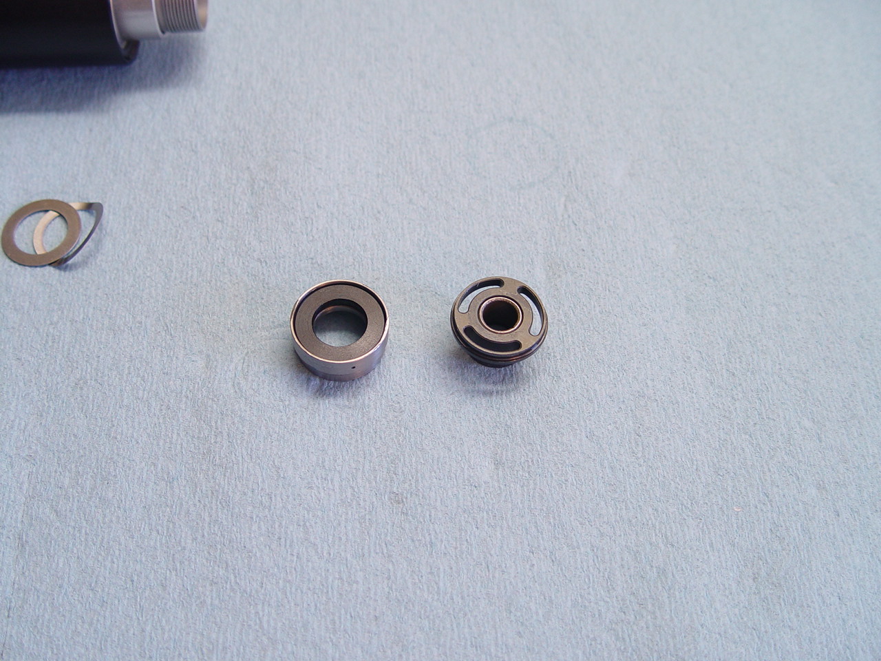
7) Reassemble icpiston and seal assembly. Use red loctite on seal assembly threads.
|
|
|
|
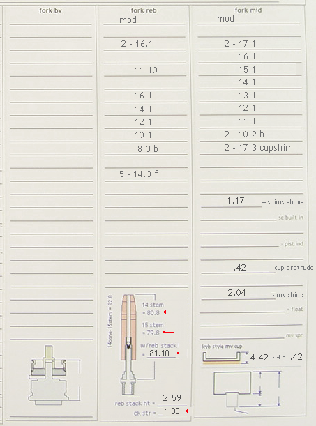
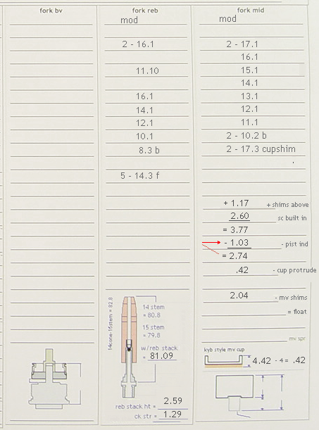
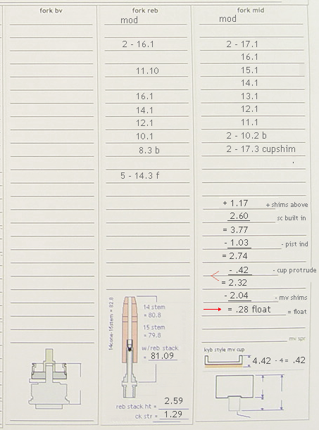
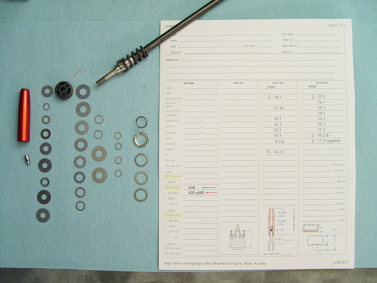
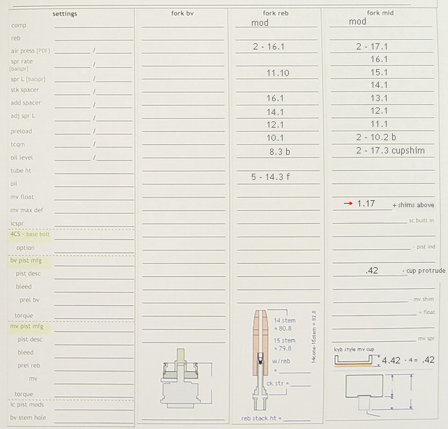
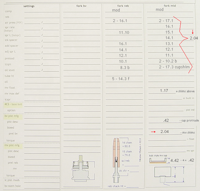
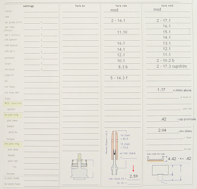
9) Mv spec sheet.
Print the 4CS spec sheet: open any record > Forms > Fork Spec Sheet - 4CS mv cup
---> Notice this build uses the KYB YZ 85 mv piston, and this is recorded on the spec sheet.
We also use the stock '15 WP mv piston. [click picture to enlarge] |
[top] |
 |
|
|
|
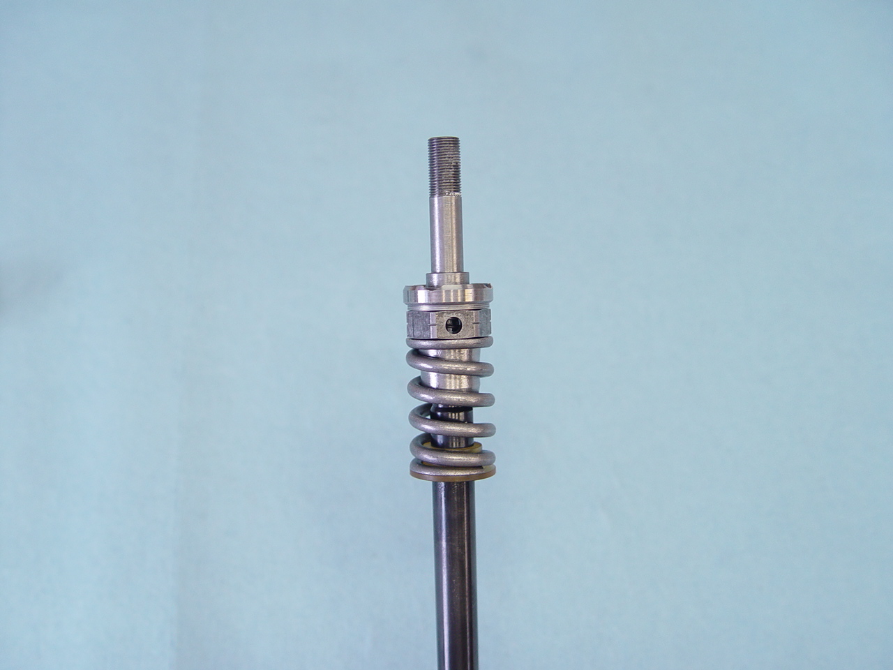
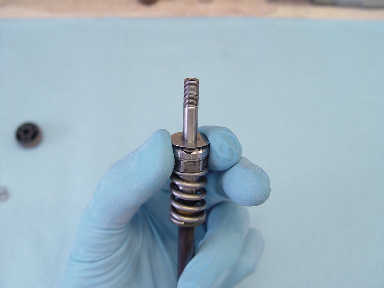
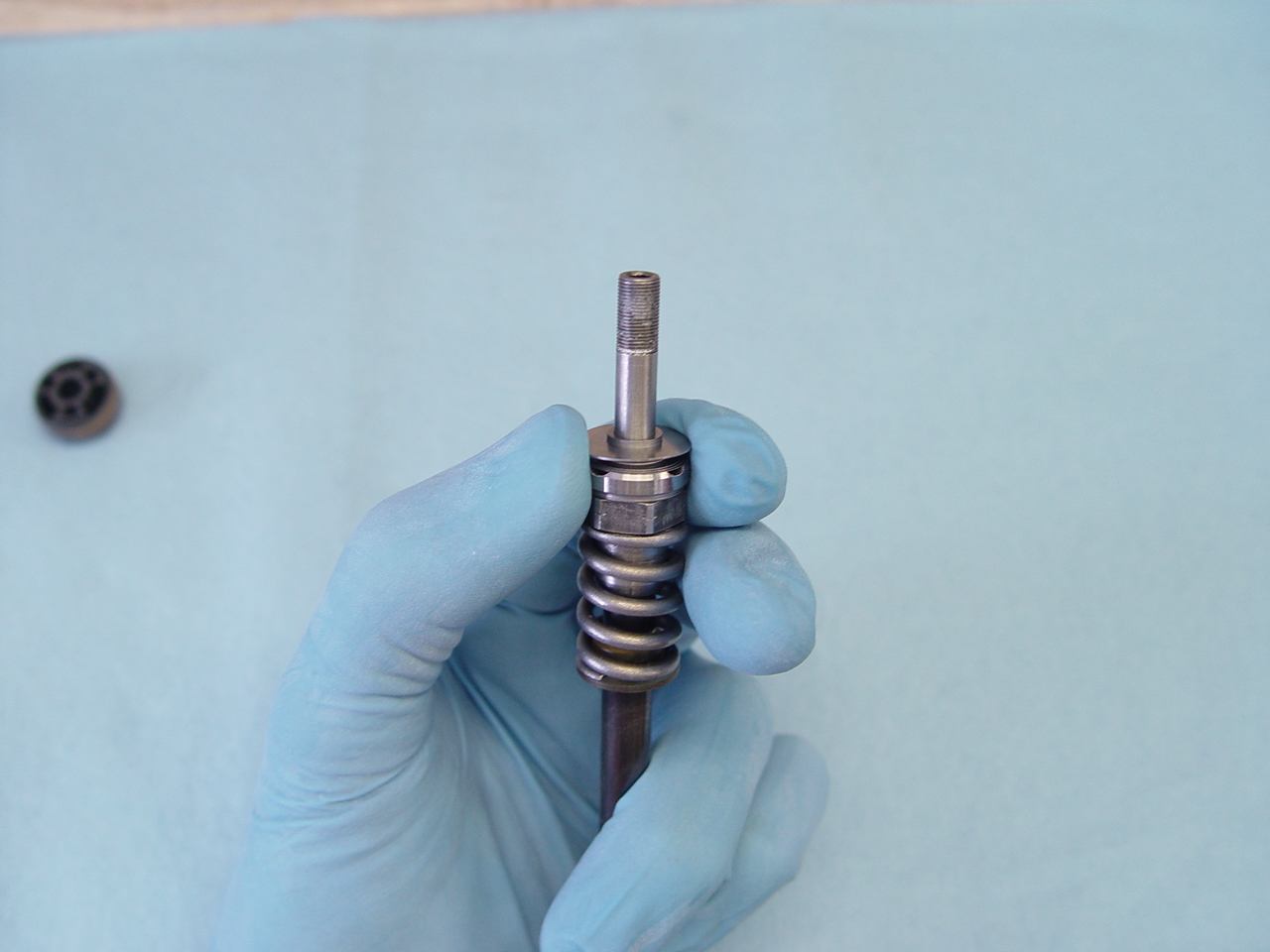
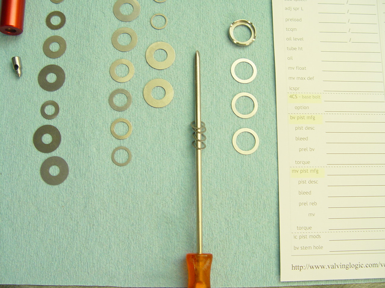
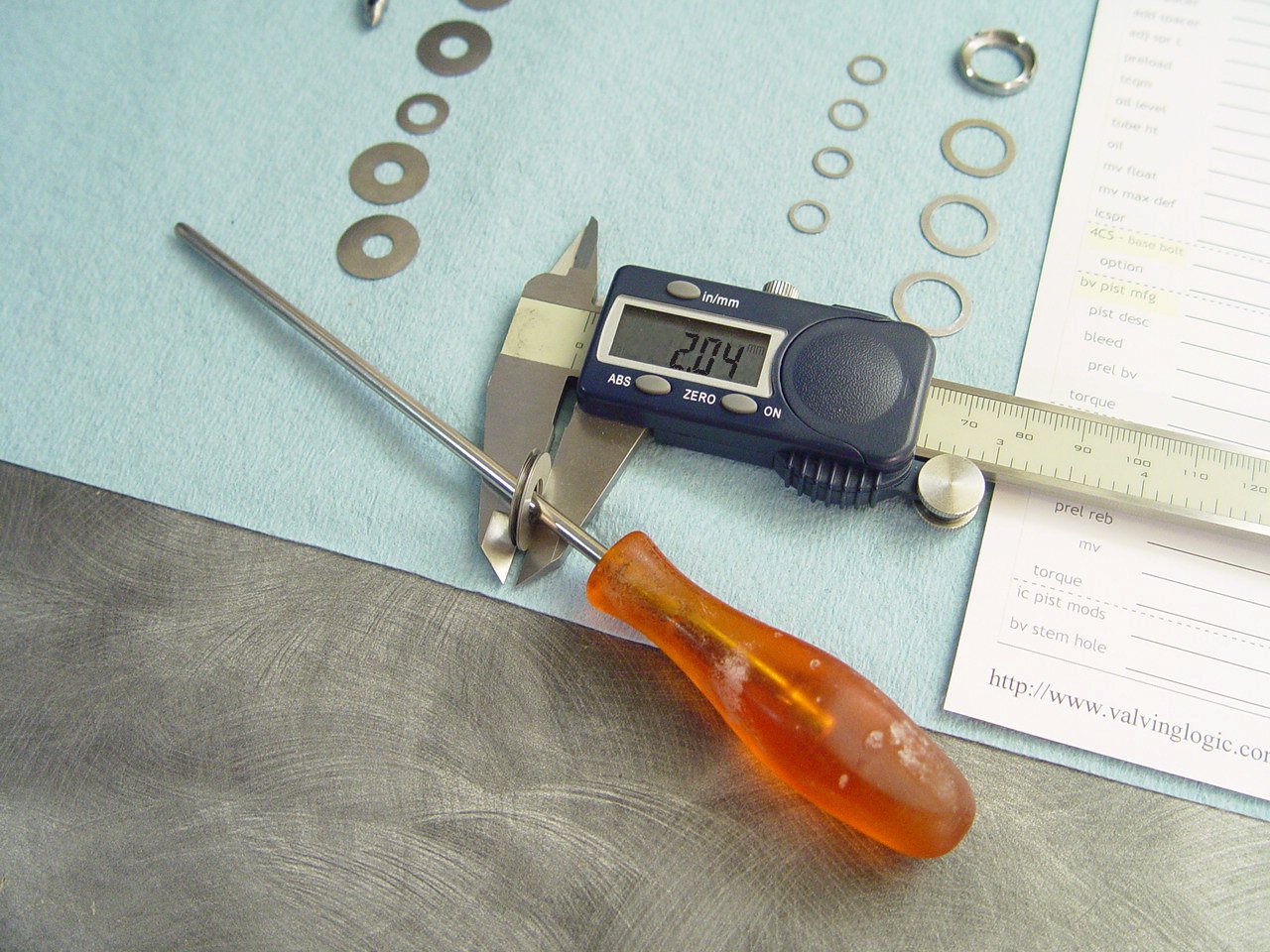
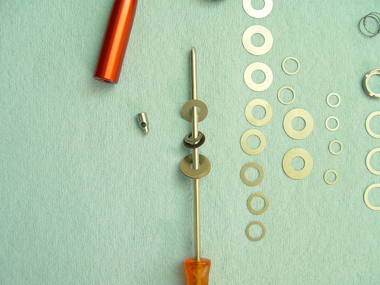
10) Measure and install the mv cup and shims under the cup.
---> This is used to determine mv float. |
[top] |
 |
String the pieces on screw driver shank, spray with contact cleaner and blow with air hose.
It's important to build the mv with the intended float. The most accurate and repeatable way is to measure the shim stacks and related pieces as shown in steps 10-11-12-13.
|
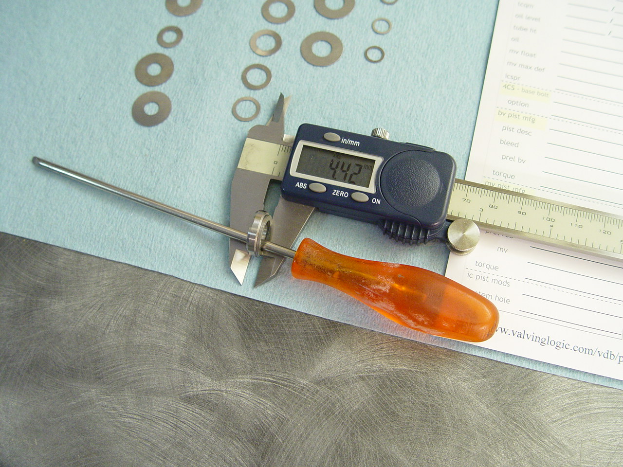 |
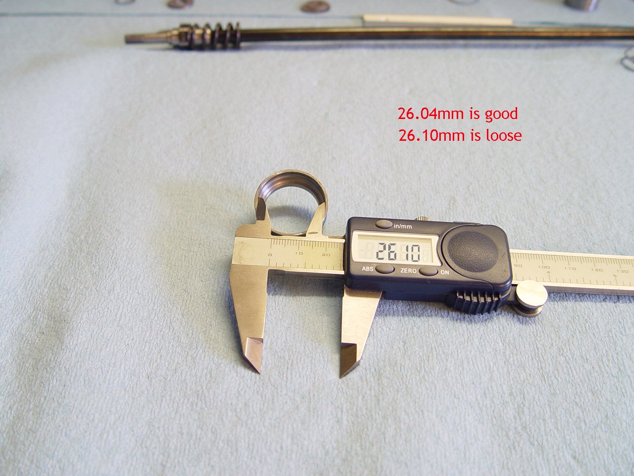
Measure thickness and record.
The supplied mv cup and 3 - 15.3 shims will always measure 4.42mm. |
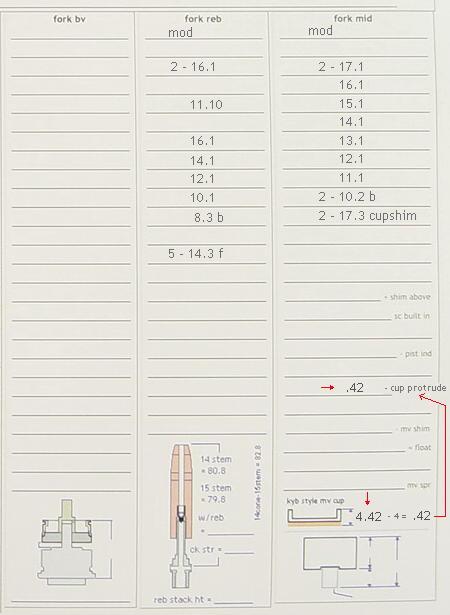 |
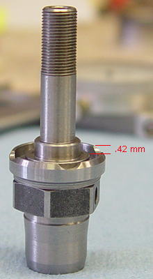
This shows the cup protrudes .42mm above the 11mm collar on mv stem.
This is used to determine the mv float.
 |
|
|
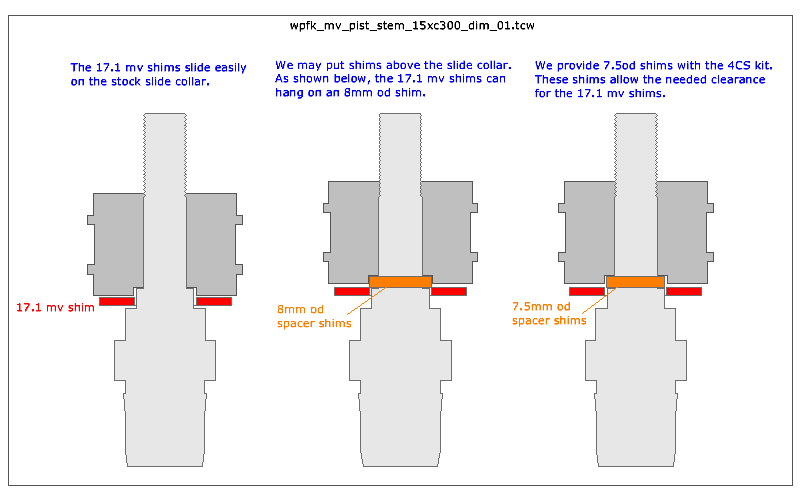
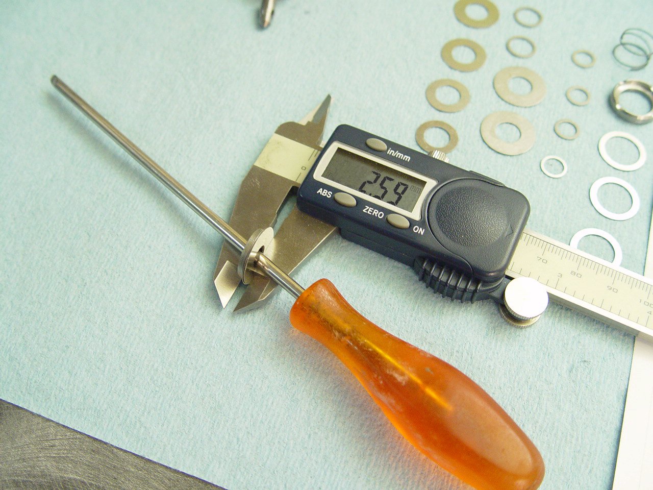
11) Measure thickness of 7.5mm od shims* that fit above the slide collar.
[* 7.5 od shims are supplied with kit. See section 14 for details]
---> This is used to determine mv float. |
[top] |
 |
String the shims, spray with contact cleaner and blow with air hose.
For accurate measurements, it is important to spray with contact cleaner and blow with air hose. |
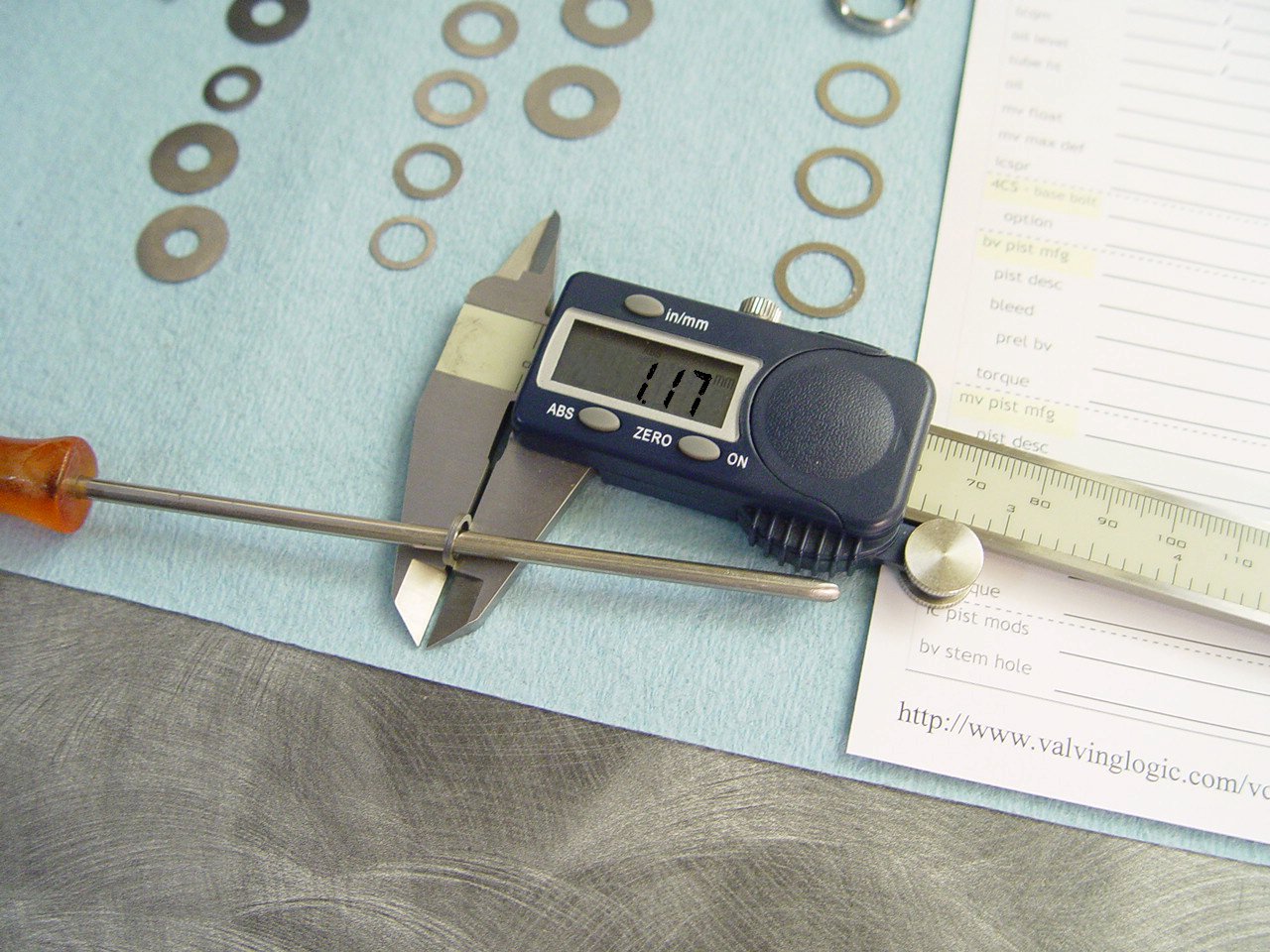 |
Measure thickness and record. |
 |
Note location of measurement. |
|
|
12) Measure and install the mv shims.
---> This is used to determine the mv float.
|
[top] |
 |
String the shims, spray with contact cleaner and blow with air hose. |
 |
Measure thickness and record. |
 |
Note location. |
|
|
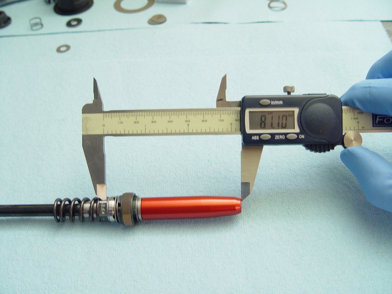
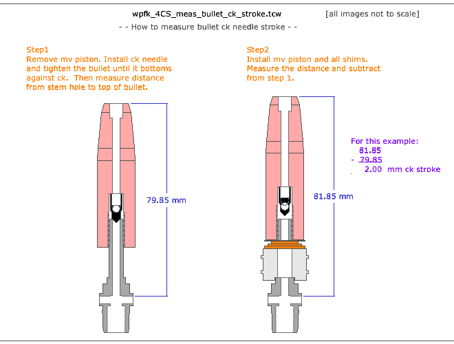
13) Measure and install the rebound shims.
---> This helps determine the bullet check needle stroke.
|
[top] |
 |
String the shims, spray with contact cleaner and blow with air hose. |
 |
Measure thickness and record.
The reb stack thickness is not critical. This measurement is only used to determine bullet check needle stroke. |
 |
Note location. |
|
|
|
|
|
|
|
|
|
|
18) Drill stock connecting nut.
|
[top] |
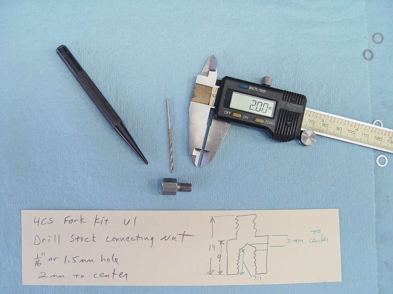 |
Drill 2 holes on opposite sides of the stock connecting nut. Use aprox 1/16 or 1.5mm bit.
This is required on the 14 and 15 models. The 16 has a regular nut and does not require drilling.
|
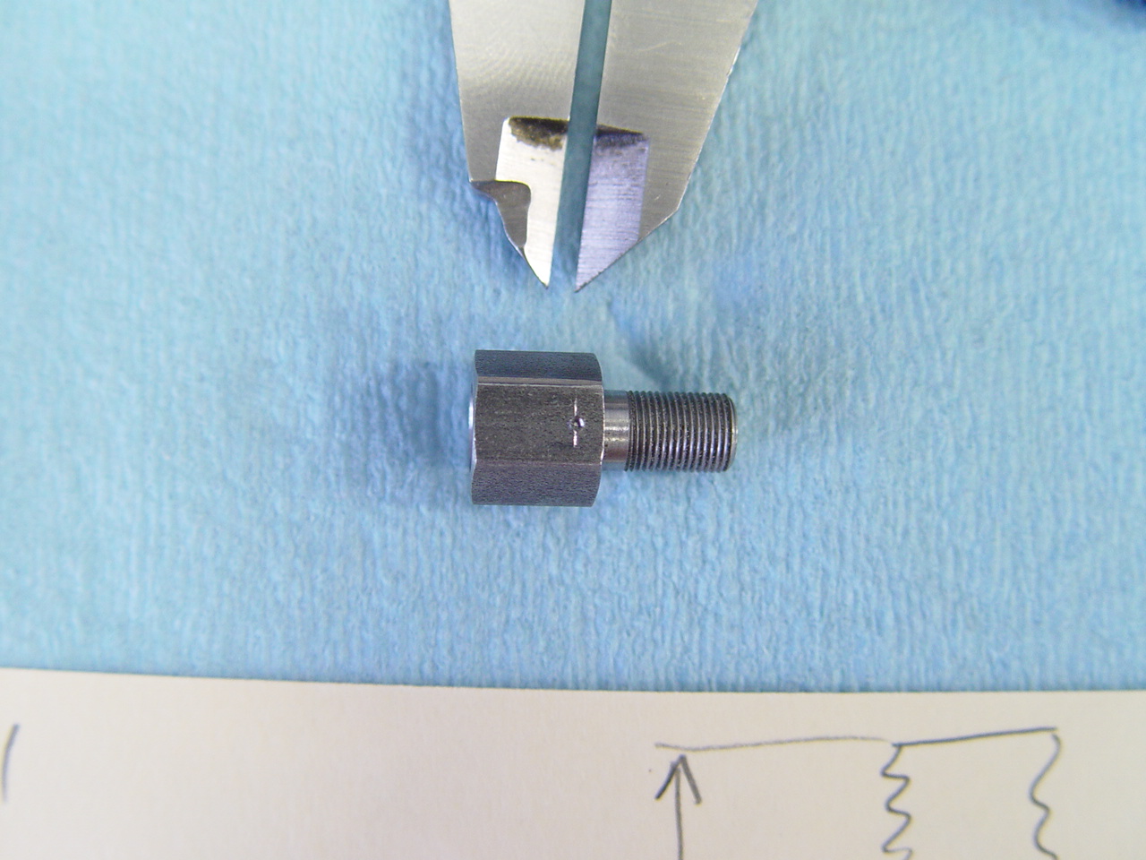 |
Use dial caliper and scribe a mark 2mm down. Use center punch to mark location for drill.
|
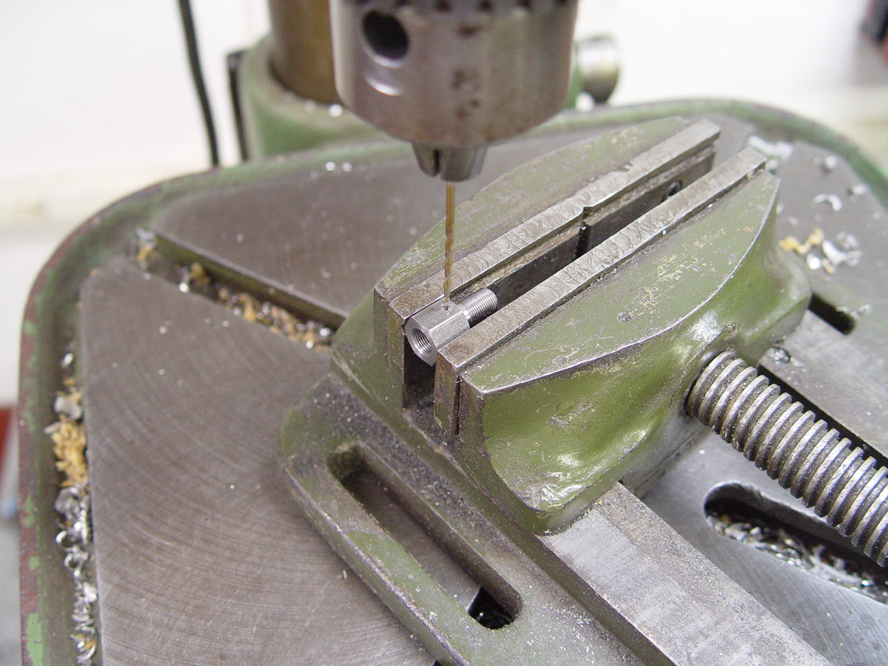 |
Secure the connecting nut in drill press vise. Drill slowly, especially when the hole is nearly through.
|
|
|
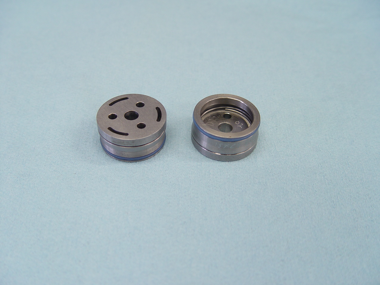
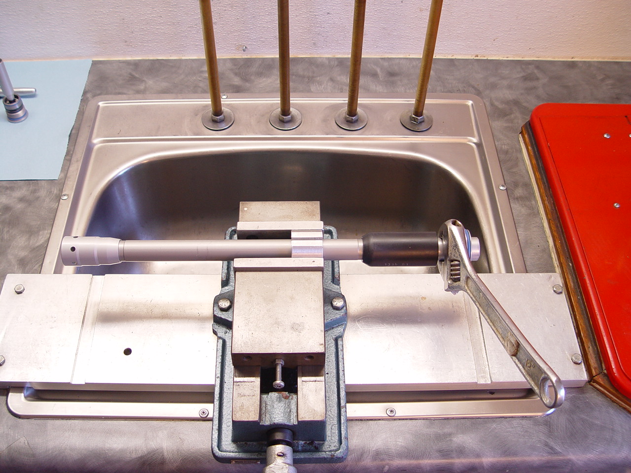
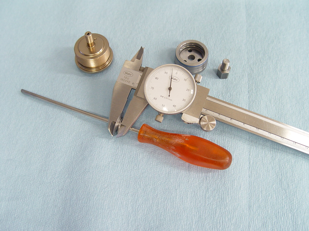
19) Assemble base valve.
---> These instructions are specific to the gp adj base bolt. |
[top] |
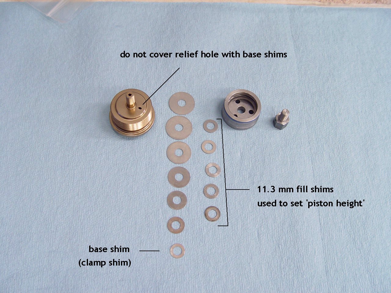 |
Do not cover the relief hole. Use max 11mm base shim.
The base bolt will accept a low speed shim stack.
|
 |
Measure the thickness of the bv stack. The stack thickness must fit within a specific range. We use:
--> bv stack thickness range = 2.3 to 3.8 mm
--> we generally set the stack height around 2.35 mm
|
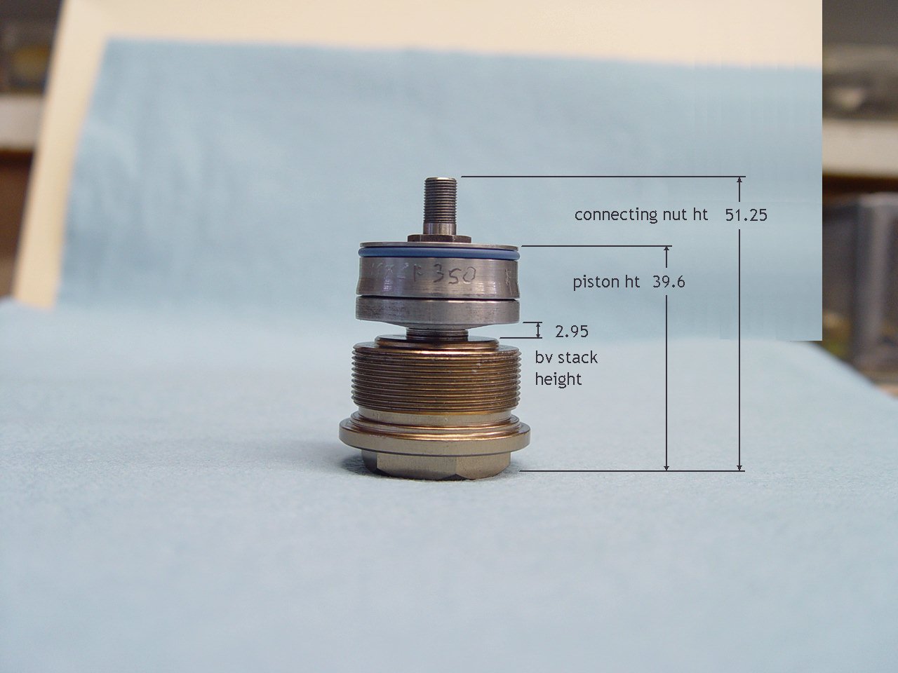 |
The assembled bv piston height must fit within a specific range. In this example:
- - bv stack thickness = 2.95 mm
- - piston ht = 39.6 mm
- - connecting nut ht = 51.25
Use loctite and torque the nut 30 in/lbs.
|
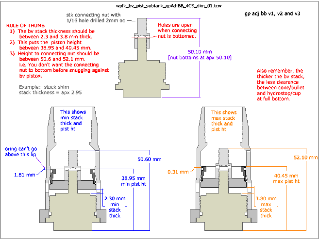 |
This diagram shows the minimum and maximum range for the bv stack thickness and piston heights.
|
|
|
| |
| |
| |
| |
| |